Document control
| Field | Value |
|---|---|
| Document summary | RemigoOne Go&DE2 Interface and Battery Service Manual |
| Document ID | |
| Version | 0.2 |
| Project | RemigoOne Go&DE2 |
| Authors | Jan Rudolf |
| Release date | |
| Approved by | |
| Approval date | |
| Status | draft |
Revision history
| Date | Version | Description | Author | Status |
|---|---|---|---|---|
| 21.6.2026 | 0.1 | Initial draft | Jan Rudolf | draft |
| 14.7.2026 | 0.2 | Restructured into Disassembly/Check/Reassembly with safety notes and non-reusable part markers | Jan Rudolf | draft |
Purpose
This document provides service instructions for interface removal, battery removal, cable duct removal, battery installation and interface sealing on the Remigo outboard. It defines the required disassembly, inspection, assembly, tools, parts, consumables and procedure-specific precautions needed to service the assembly correctly.
WARNING
Read Safety instructions before starting.
- Remove the kill switch before starting any service procedure to prevent accidental motor start.
- Disconnect the battery before working on any electrical components.
- Never short-circuit, puncture, crush or deform the battery pack.
- Wear nitrile gloves when handling silicone/adhesive and when handling the interface during and after degreasing.
- Do not cut deeper than 2-3 mm when cutting silicone around the interface. Use only plastic tools on the sealing surface.
- The motor controller (PCBA) is ESD-sensitive.
Required parts
- 🗑 Interface assembly GO (120020002) / Interface assembly DE2 (120020003) (select the correct variant for the unit) — not reusable once removed
- 🗑 Battery pack (706020002) — not reusable if swollen/damaged (see Check section)
- Motor housing assembly
- Plastic cable duct (060040002)
- Battery fixing plate (045010003)
- Screw M4x25 TX20 (ISO14581-M4X25-A4_TX20)
- Cable protection plastic
Required consumables
- Isopropanol
- Silicone Dowsil 7091 (010010001)
- Rubber gloves
- Paper towel
- Mild window cleaner
Required custom tools
Required standard tools
- T20 Torx driver
- Bungie cord
- Needle-nose pliers
- Silicone Squeegee
- Exacto knife
- Razorblade
- Silicone dispenser
Interface and battery disassembly
IB-DIS-001 DISASSEMBLY STEP 1 - Cut silicone around interface
Tools:
Removing parts:
- No parts removed in this step.
Procedure:
- Place the transom bracket and outboard on a stable holder.
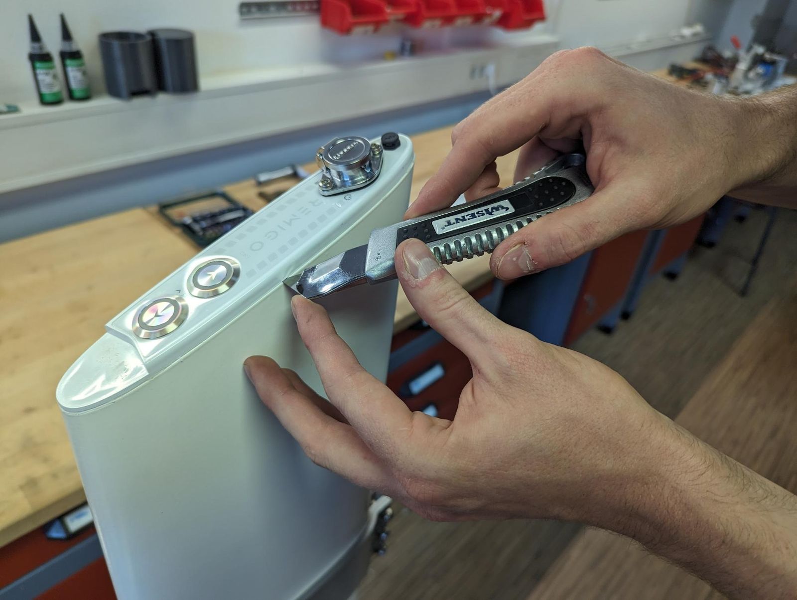
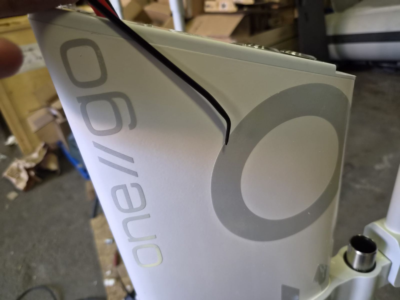
- Cut under the interface to a depth of 2-3 mm around the interface edge.
Link to originalCAUTION
Do not cut deeper than required. Cutting too deep can damage the interface, cables or sealing surface.
IB-DIS-002 DISASSEMBLY STEP 2 - Remove charging connector
Tools:
Removing parts:
- No parts removed in this step.
Procedure:
Link to original
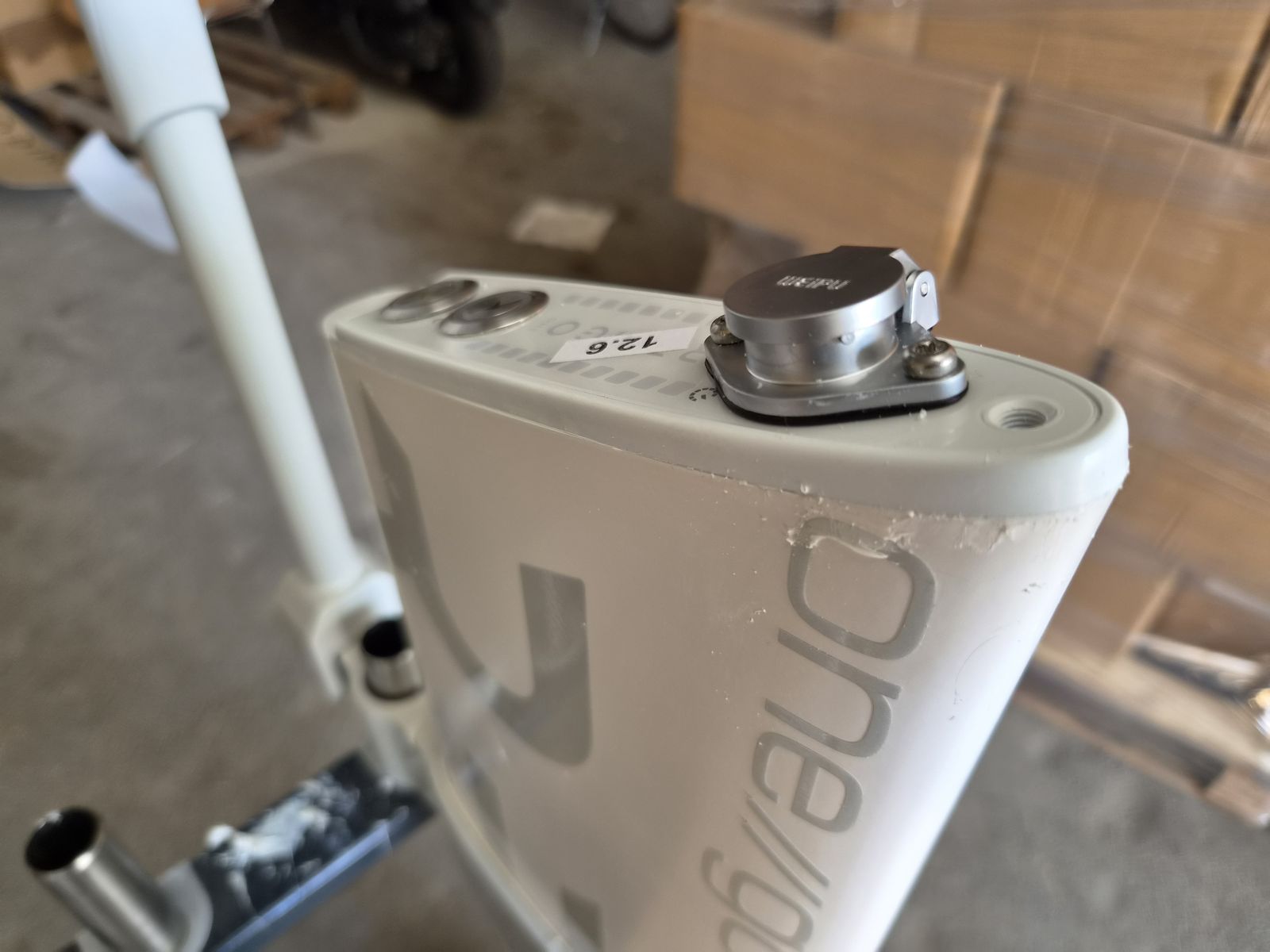
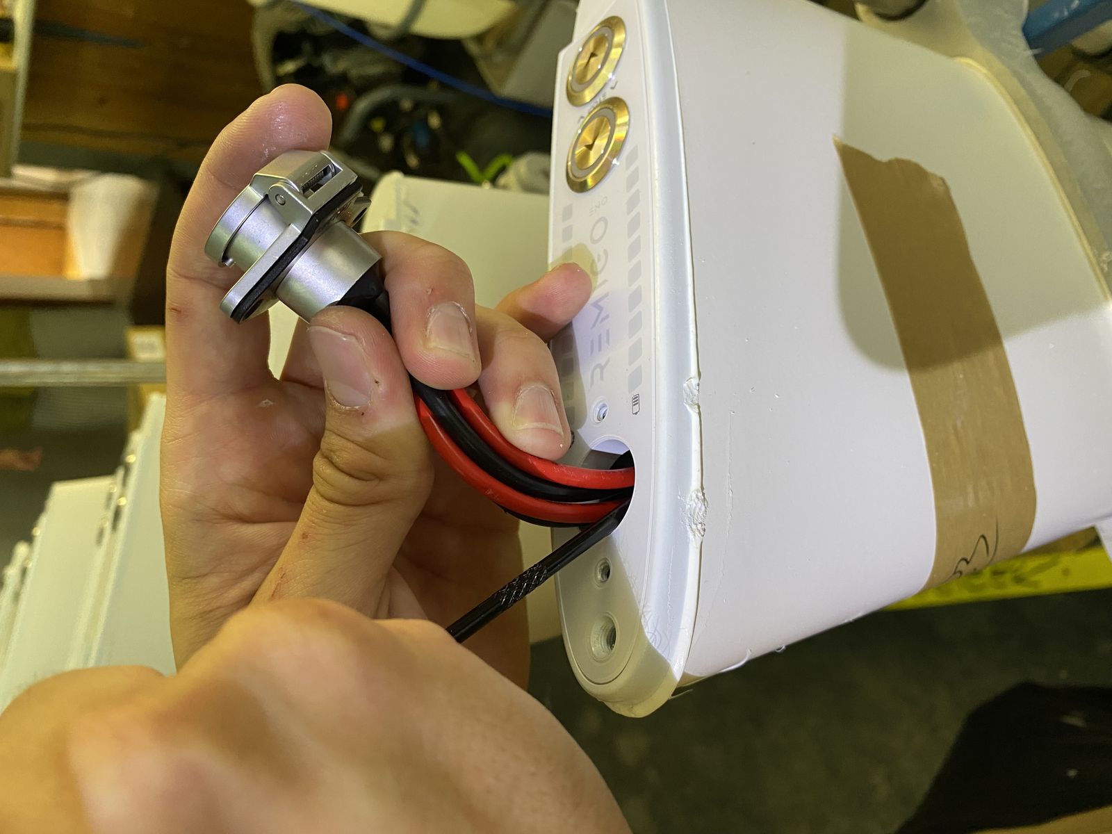
- Unscrew the two screws on the charging connector cap.
- Pull the charging connector cap out of the housing.
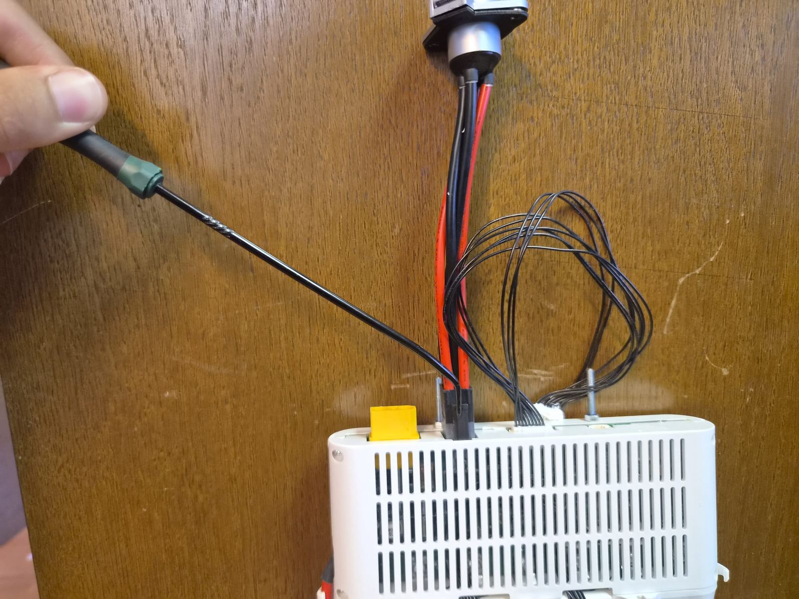
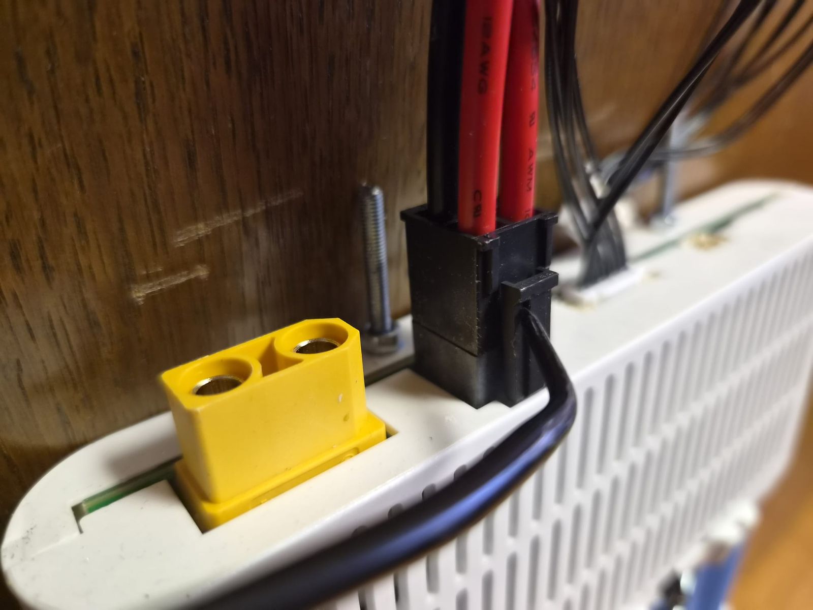
- The connector has a locking tab — use the tool to unlock the connector.
- Remove the charging connector.
IB-DIS-003 DISASSEMBLY STEP 3 - Screw in interface removal tool
Tools:
Removing parts:
- No parts removed in this step.
Procedure:
Link to original
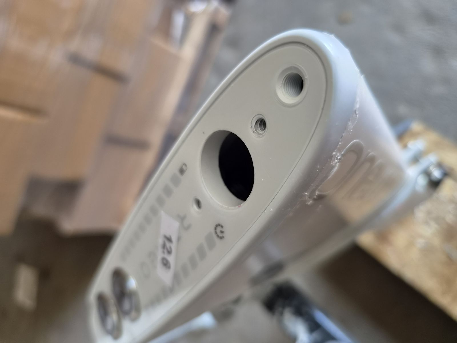
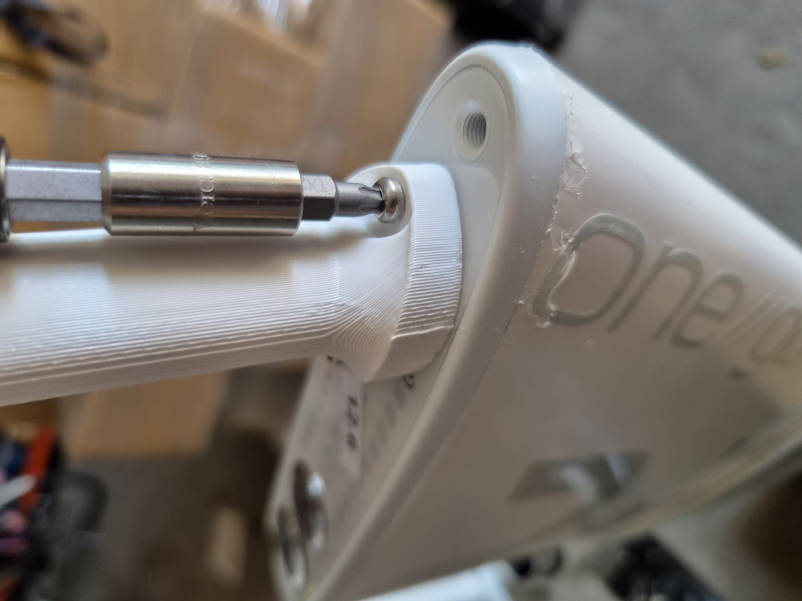
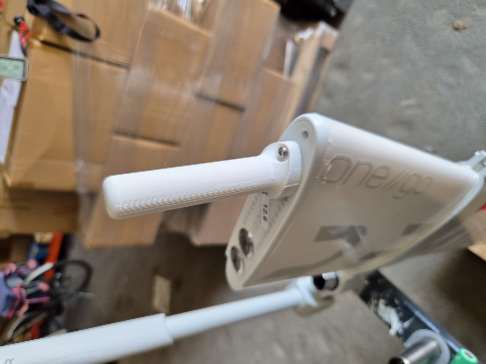
- Screw the interface removal tool (900040006) into the mounting holes next to the charging connector socket.
IB-DIS-004 DISASSEMBLY STEP 4 - Loosen interface
Tools:
Removing parts:
- No parts removed in this step.
Procedure:
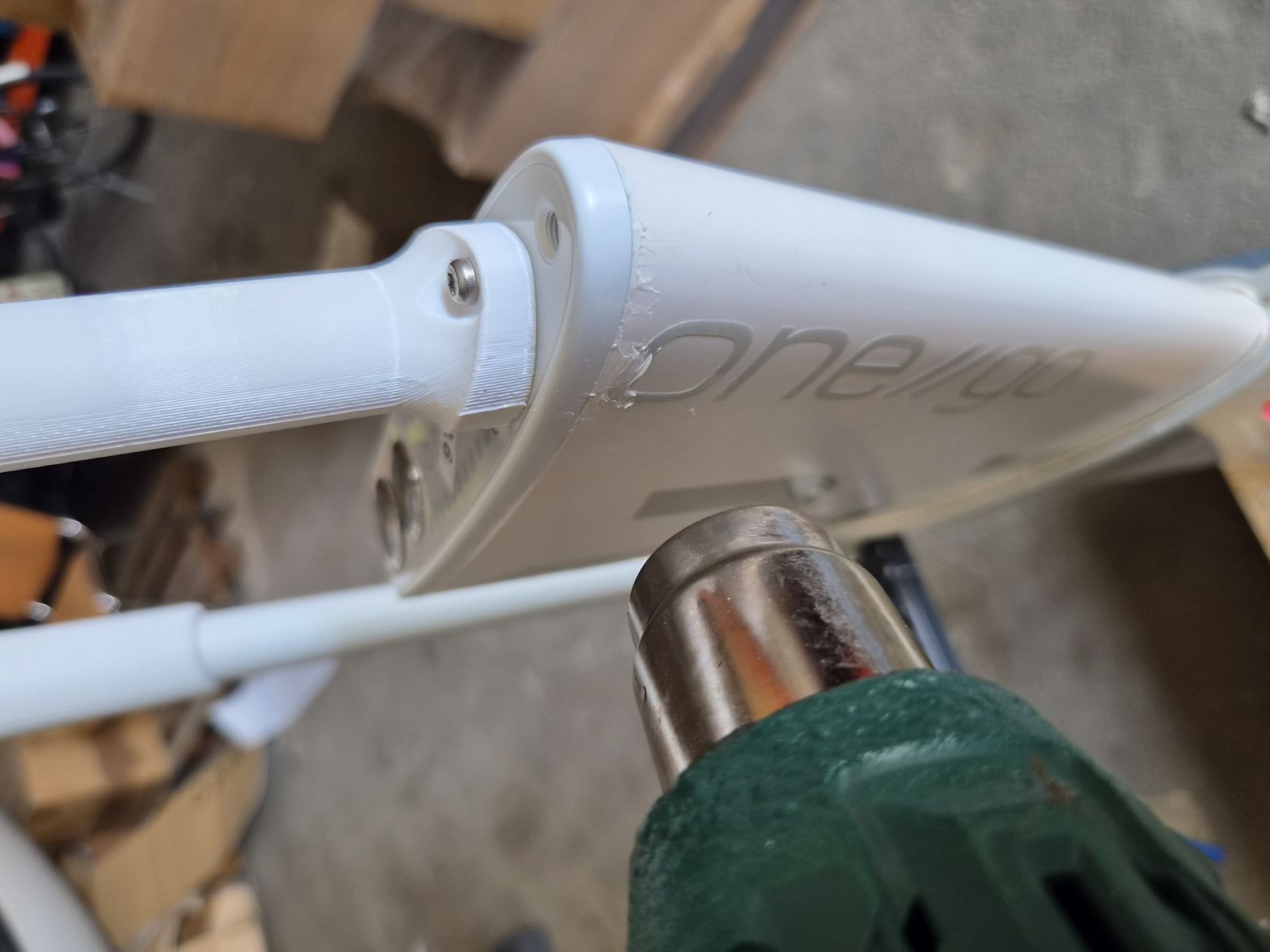
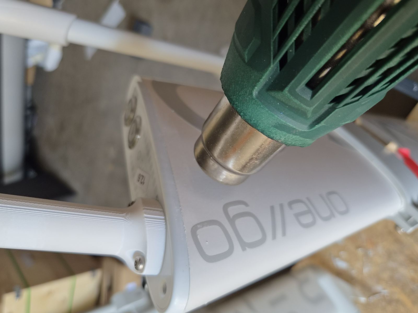
- Set the heat gun to 350°C and heat around the interface joint to soften the silicone.
- Move the interface removal tool left, right, up and down until the interface breaks free from the silicone.
CAUTION
Use only a plastic tool on the sealing surface. Metal tools can scratch the housing and cause leakage after assembly.
Link to originalNOTE
The interface is not reusable once removed and must be replaced — see IB-DIS-005 DISASSEMBLY STEP 5 - Lift interface.
IB-DIS-005 DISASSEMBLY STEP 5 - Lift interface
Tools:
- No tools required.
Removing parts:
- 🗑 Interface assembly GO (120020002) / Interface assembly DE2 (120020003) (select the correct variant for the unit) (not reusable — discard after removal)
Procedure:
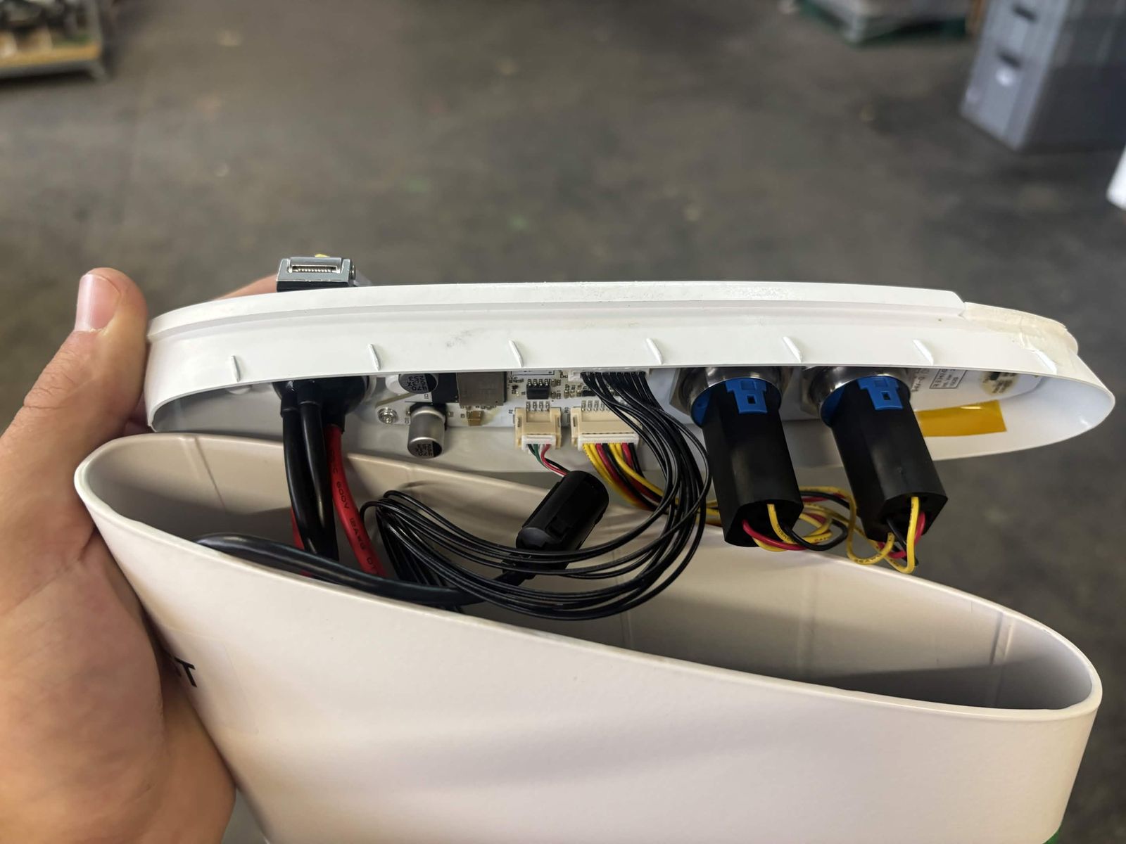
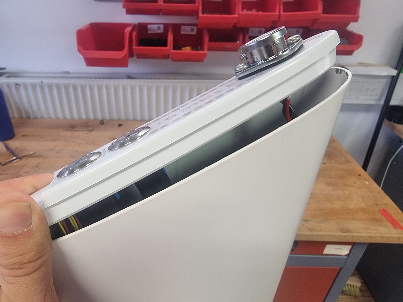
- When the silicone is loosened, lift the interface by hand.
- Lift only far enough to access the connectors.
Link to originalCAUTION
Do not pull the interface away from the housing before all connectors are disconnected.
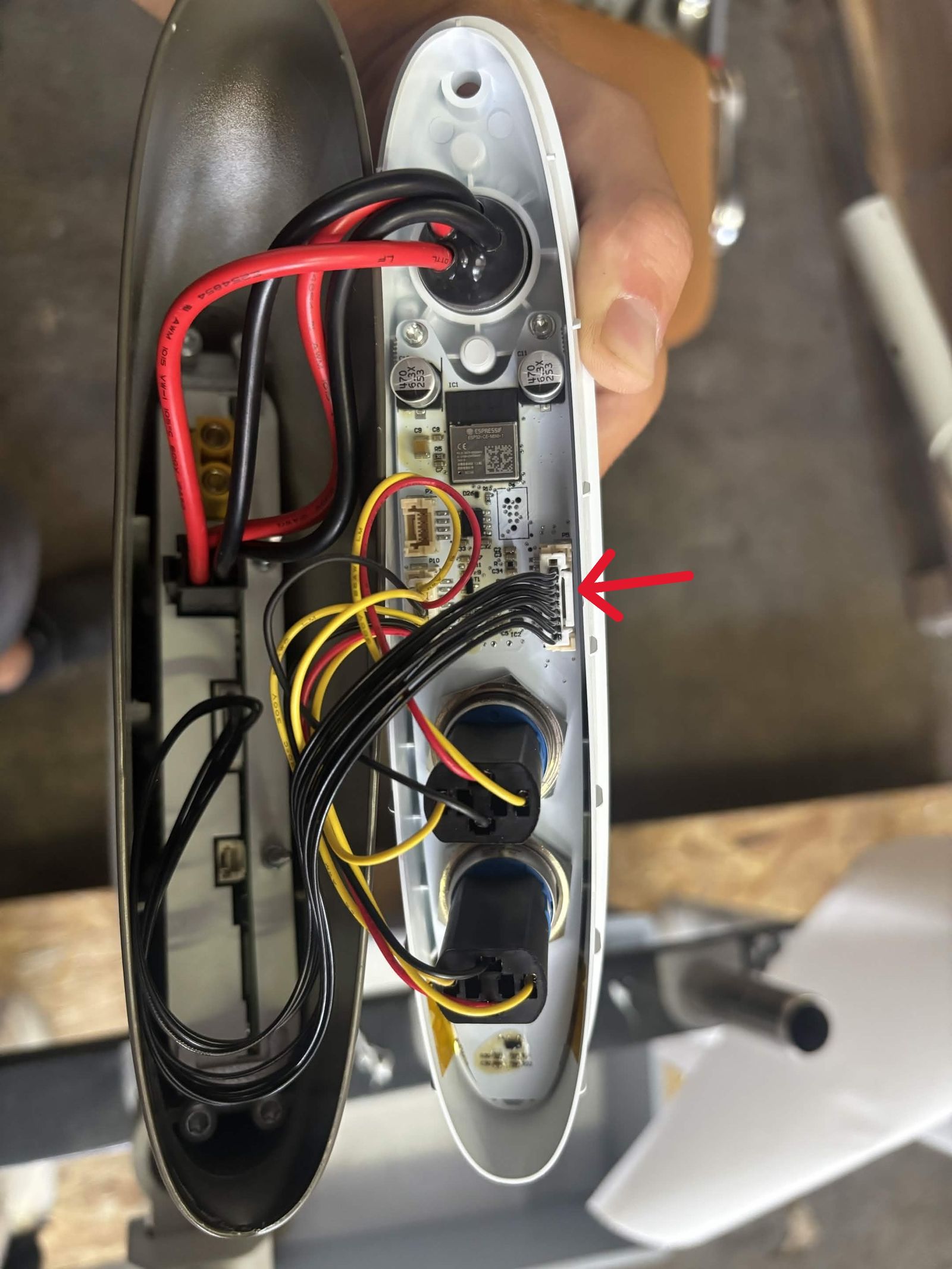
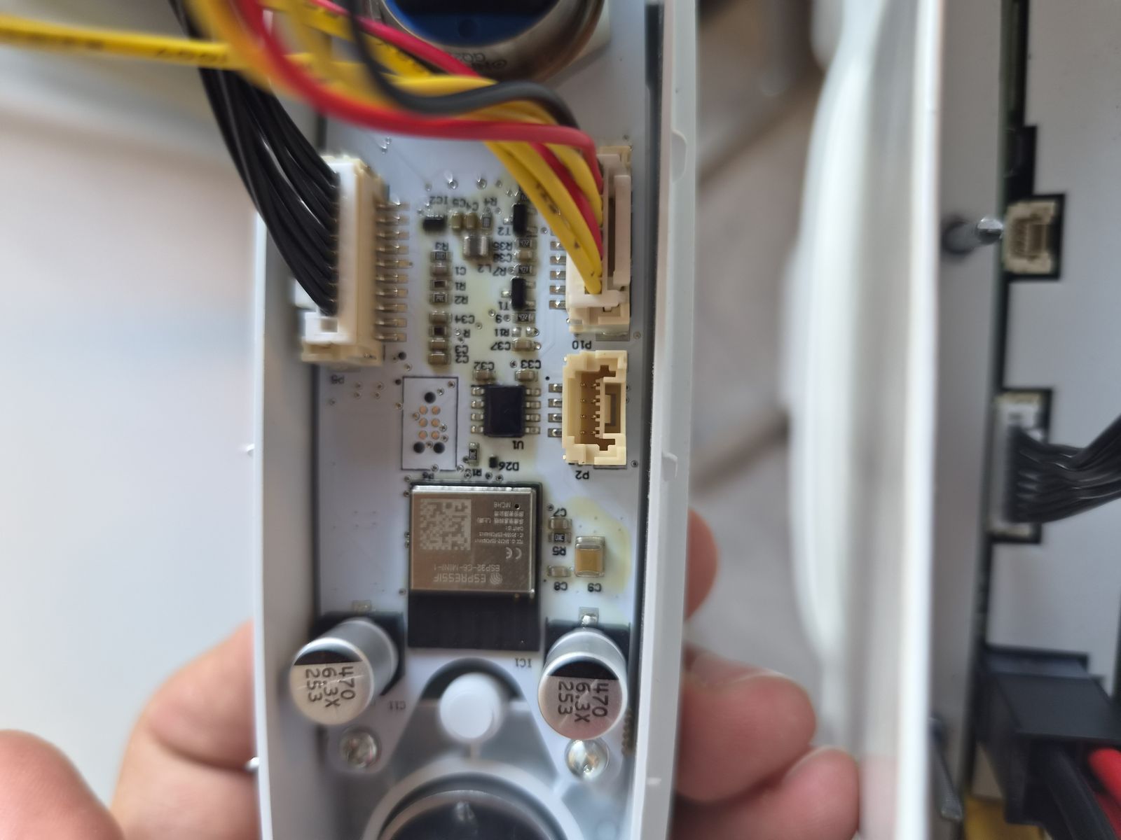
IB-DIS-006 DISASSEMBLY STEP 6 - Disconnect interface connectors
Tools:
- No tools required.
Removing parts:
- No parts removed in this step.
Procedure:
Link to original
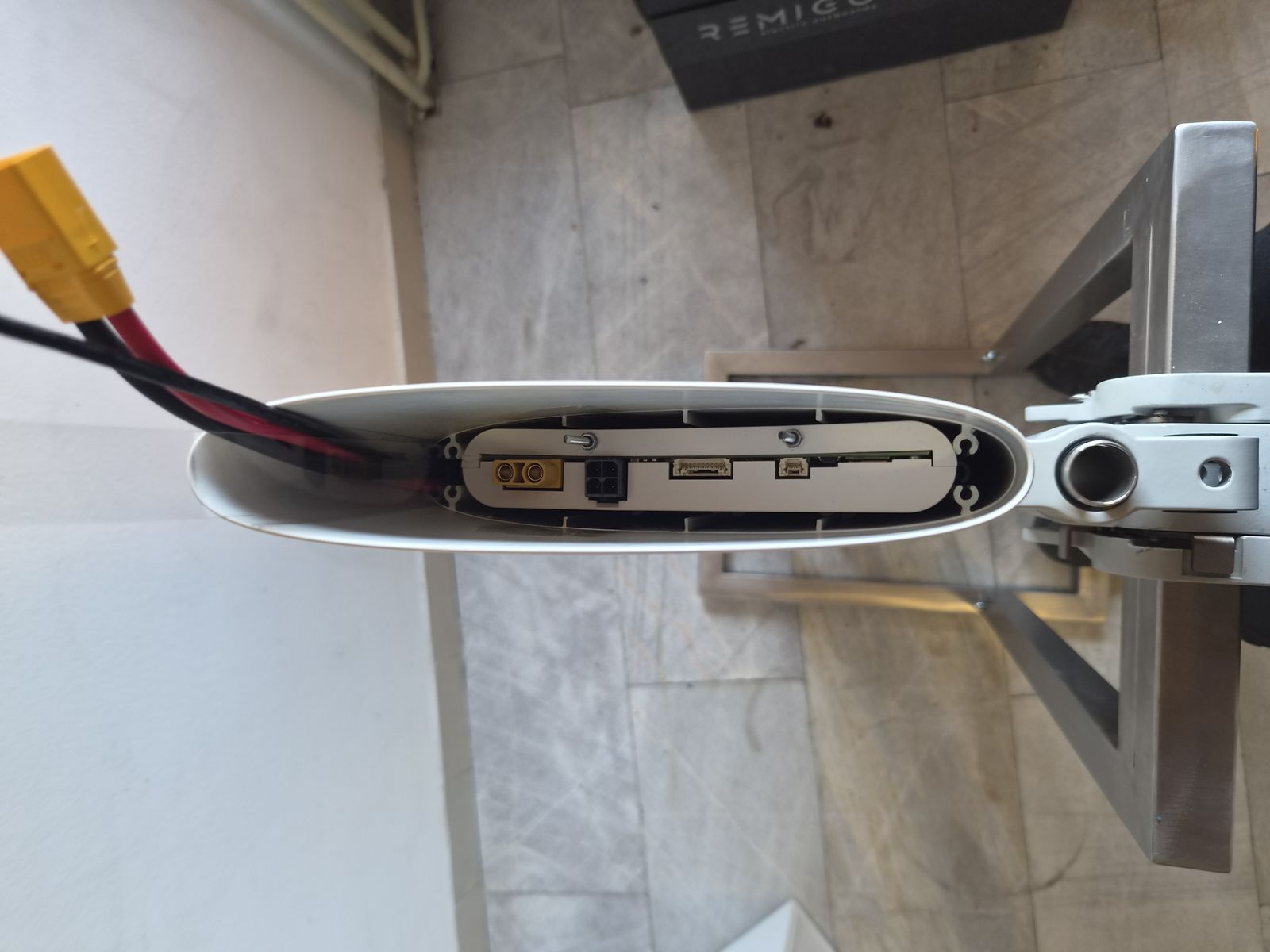
- Carefully disconnect the connectors shown in the picture.
- Some connectors have a small locking tab — release it before pulling the connector apart.
- Support the connector bodies during removal. Do not pull on the wires.
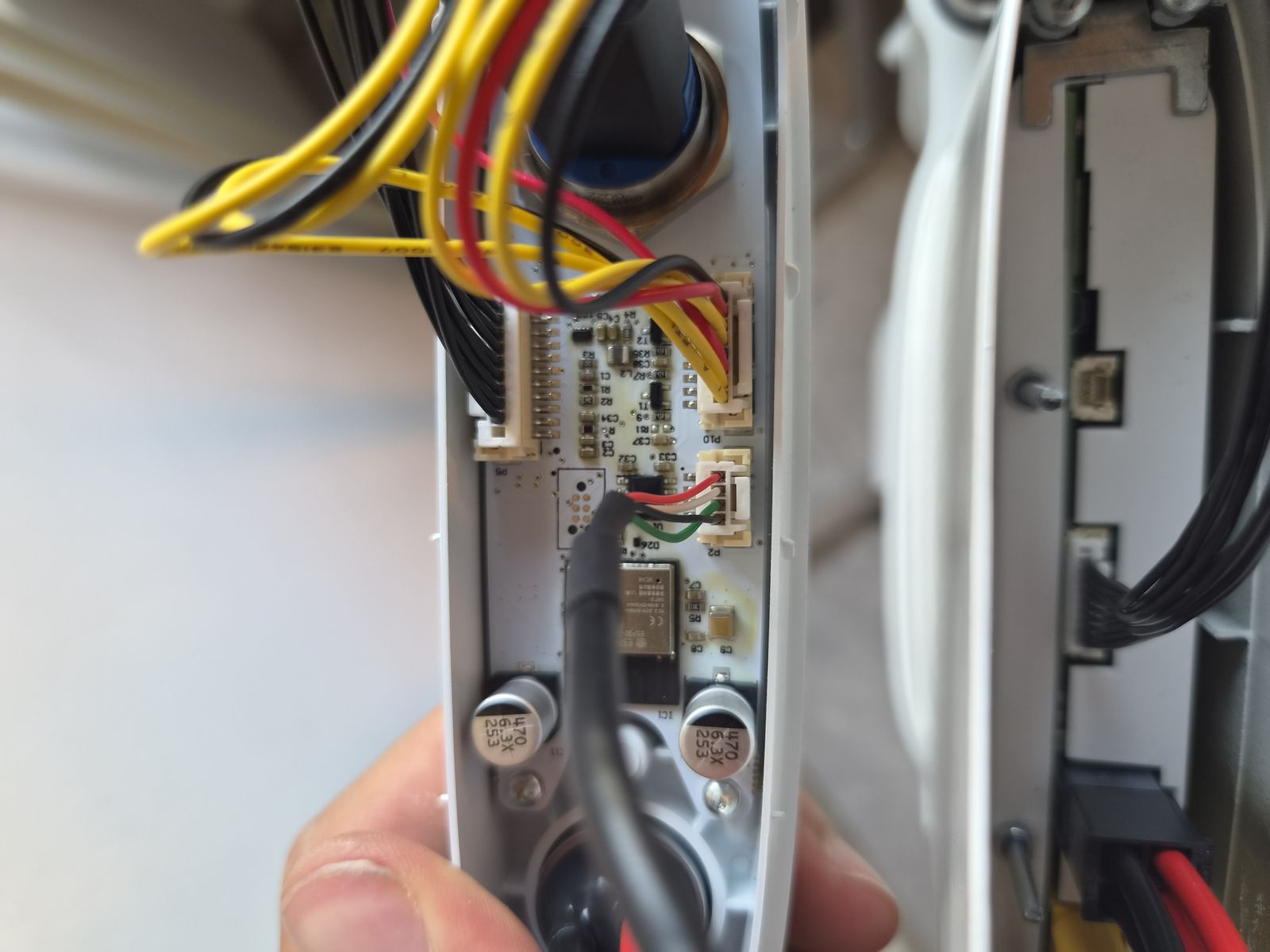
IB-DIS-007 DISASSEMBLY STEP 7 - Disconnect signal cable
Tools:
- Exacto knife, if silicone is present
Removing parts:
- No parts removed in this step.
Procedure:
- Press the small latch on the side of the connector.
- Disconnect the smaller signal cable.
- If the connector is covered with silicone, carefully remove only the excess silicone needed to release the latch.
Link to originalCAUTION
Do not cut into the connector housing or cable insulation when removing silicone.
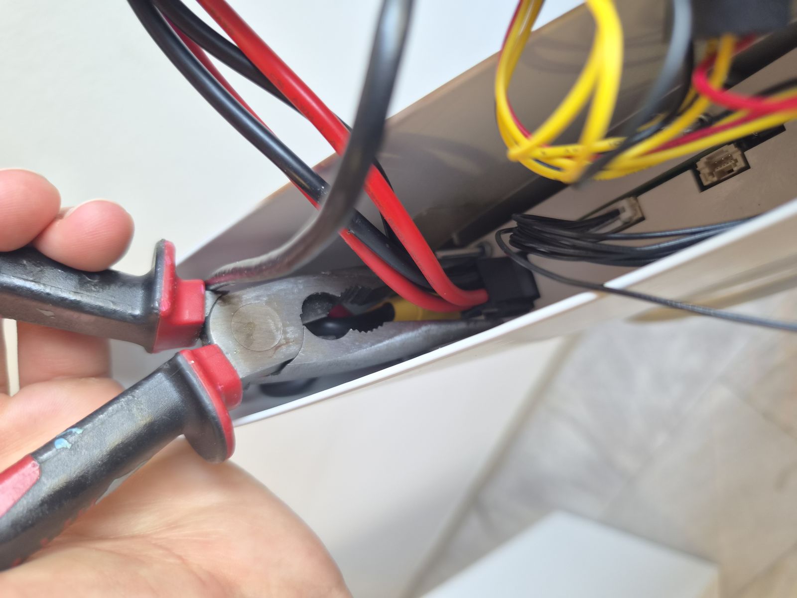
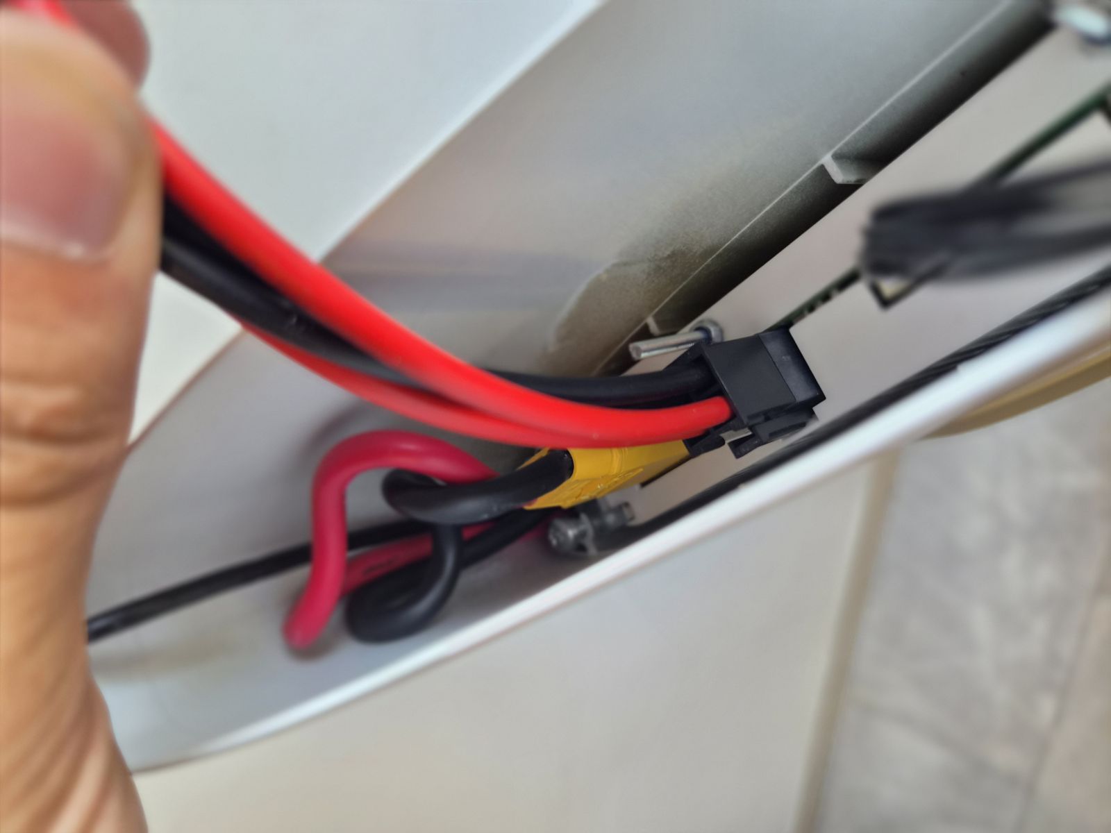
IB-DIS-008 DISASSEMBLY STEP 8 - Disconnect motor cable from battery
Tools:
Removing parts:
- No parts removed in this step.
Procedure:
Link to original
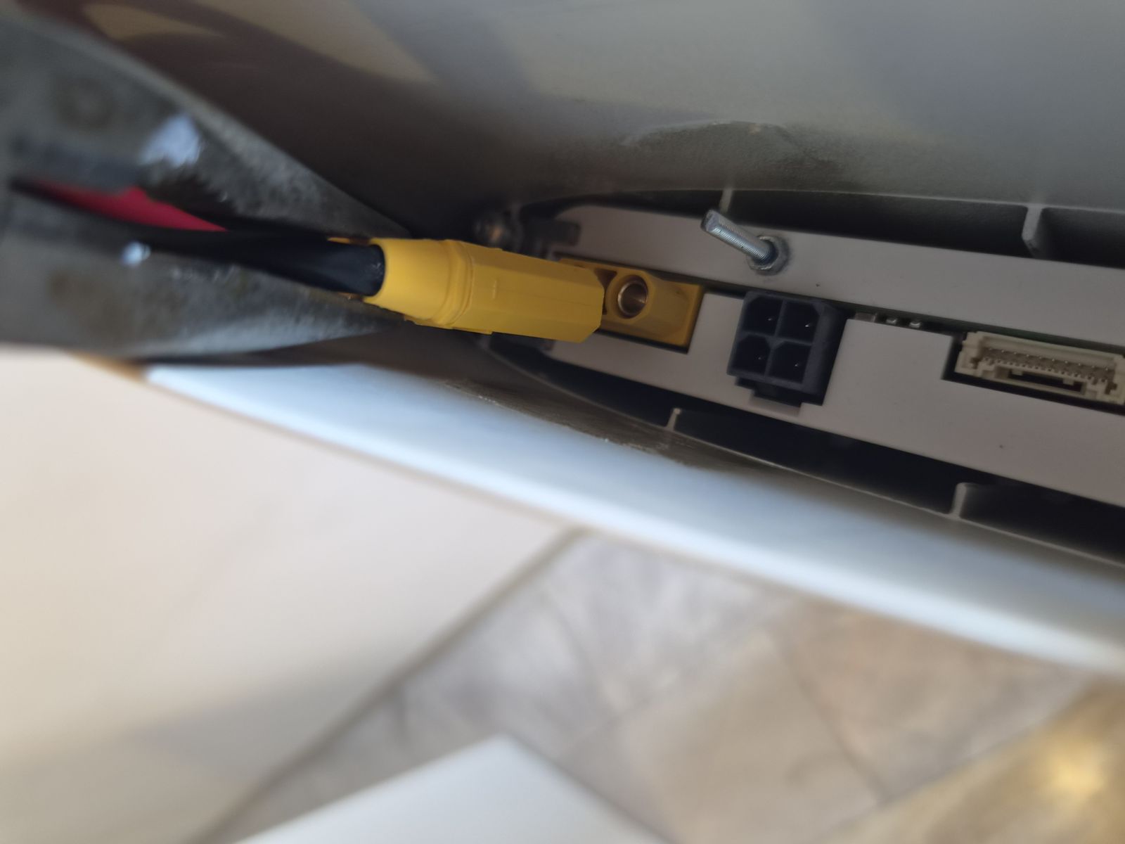
- Use needle-nose pliers to disconnect the motor cable from the battery connector.
- Pull on the connector body only.
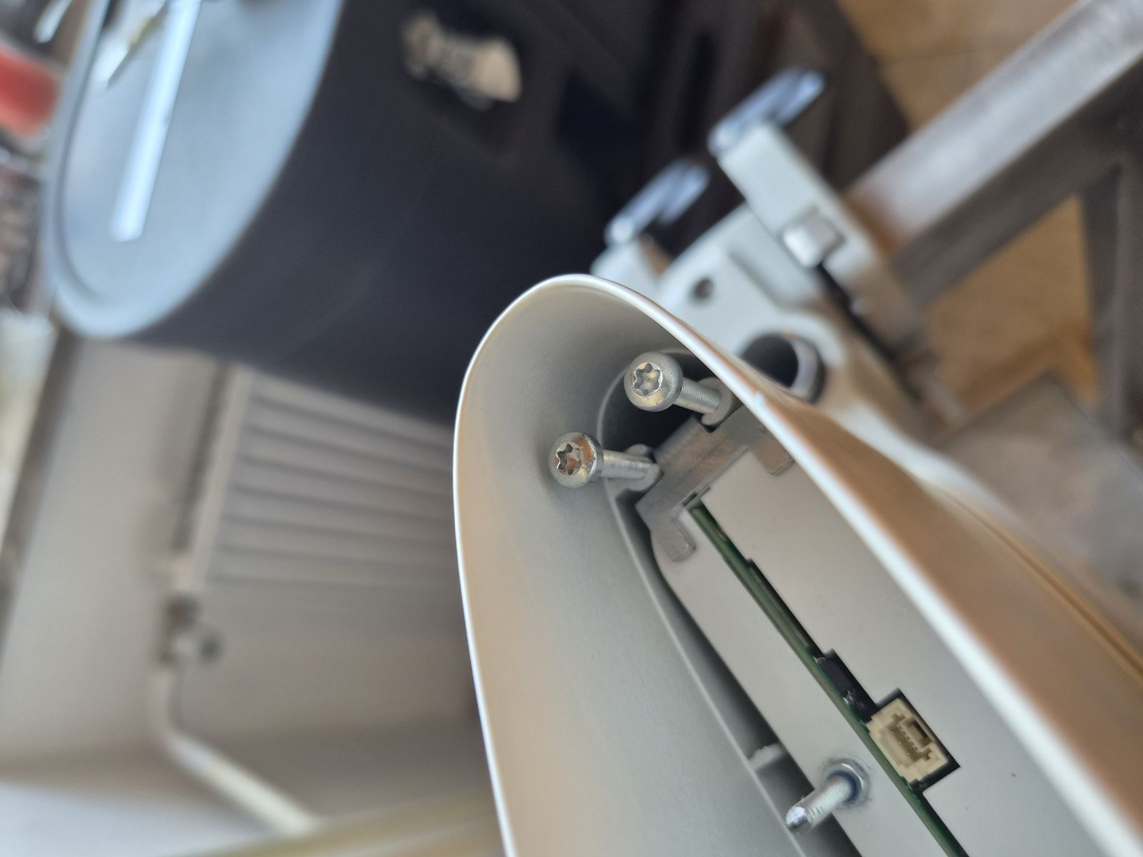
IB-DIS-009 DISASSEMBLY STEP 9 - Remove battery fixing screws
Tools:
Removing parts:
Procedure:
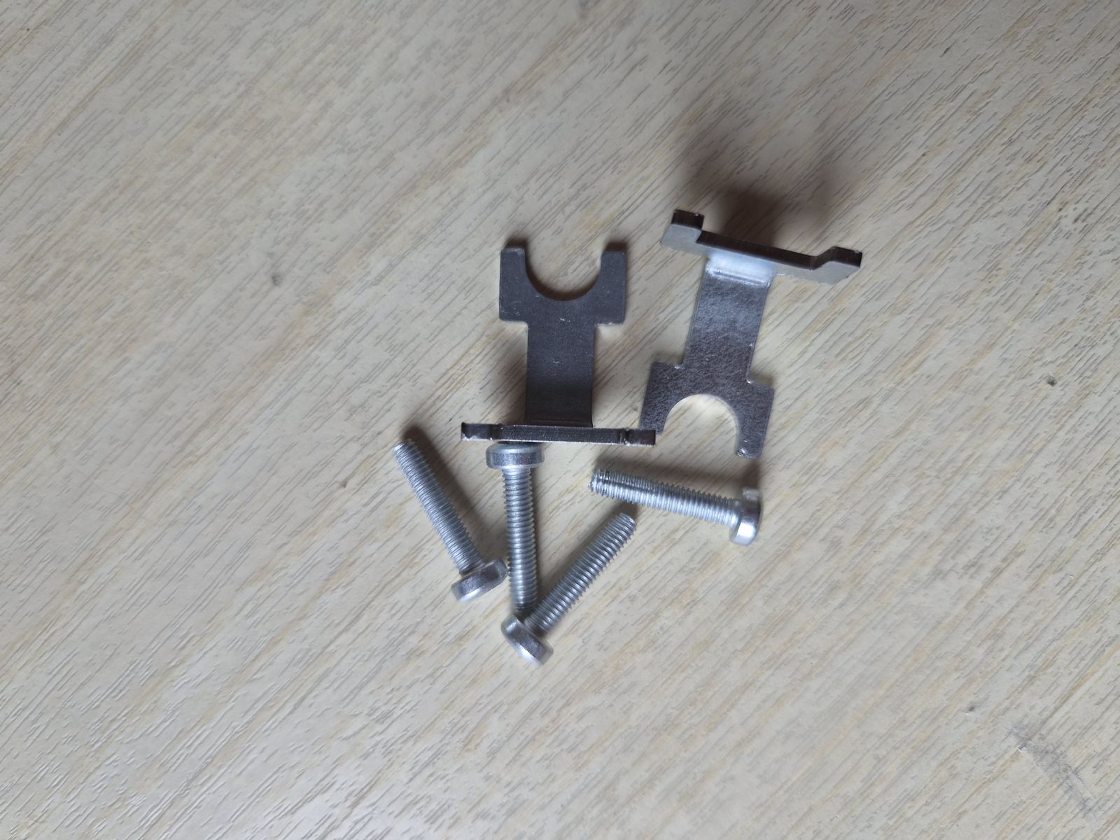
- Unscrew the four M4x25 screws.
- Remove two screws from each side of the battery.
Link to originalCAUTION
Work with the housing in a horizontal position. A dropped screw can fall into the battery or motor cavity and cause a short circuit.
IB-DIS-010 DISASSEMBLY STEP 10 - Remove battery fixing plates
Tools:
Removing parts:
Procedure:
Link to original
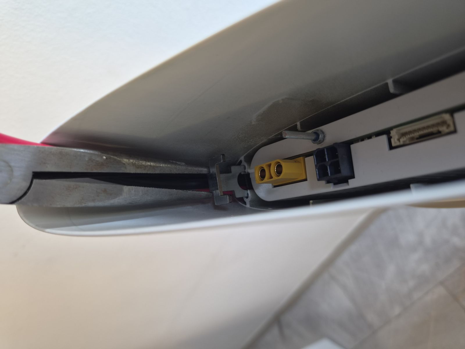
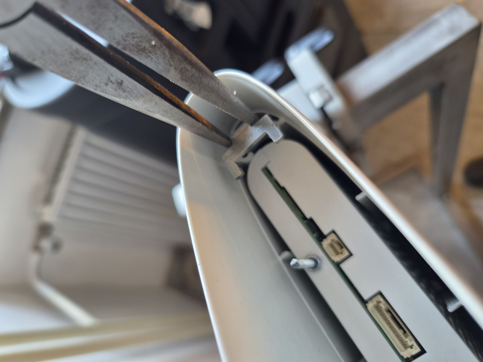
- Remove the battery fixing plate with needle-nose pliers.
- Repeat on the opposite side of the battery.
IB-DIS-011 DISASSEMBLY STEP 11 - Remove battery pack
Tools:
Removing parts:
Procedure:
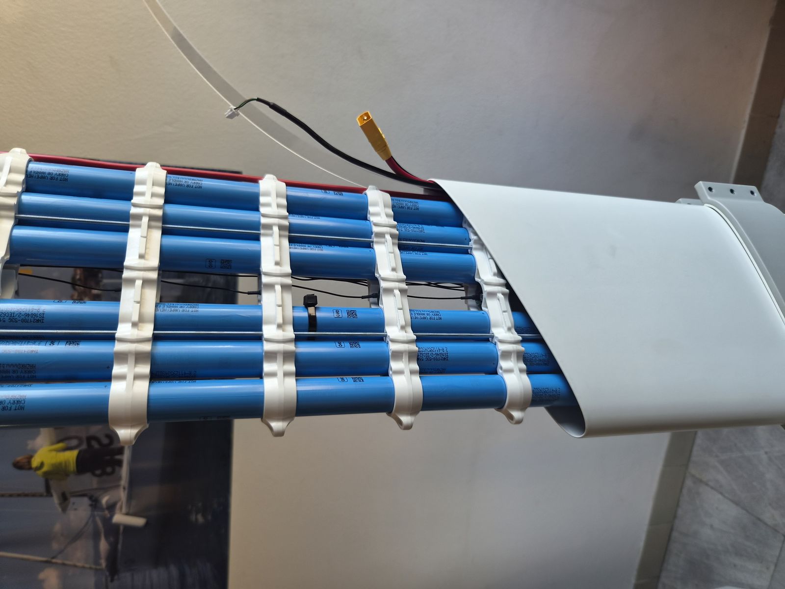
- Pull one end of the threaded rod with needle-nose pliers.
- Slide the battery pack out of the housing.
Link to originalCAUTION
Keep the battery straight during removal to avoid damaging the cables or housing channels.
IB-DIS-012 DISASSEMBLY STEP 12 - Inspect power cables
Tools:
- No tools required.
Removing parts:
- No parts removed in this step.
Procedure:
- Inspect the power cables for cuts, damaged insulation, loose terminals or other damage.
- If the cables are not damaged, leave them installed.
- If the cables are damaged, continue with the cable duct removal step.
Link to originalNOTE
The cables do not need to be removed if they are not damaged.
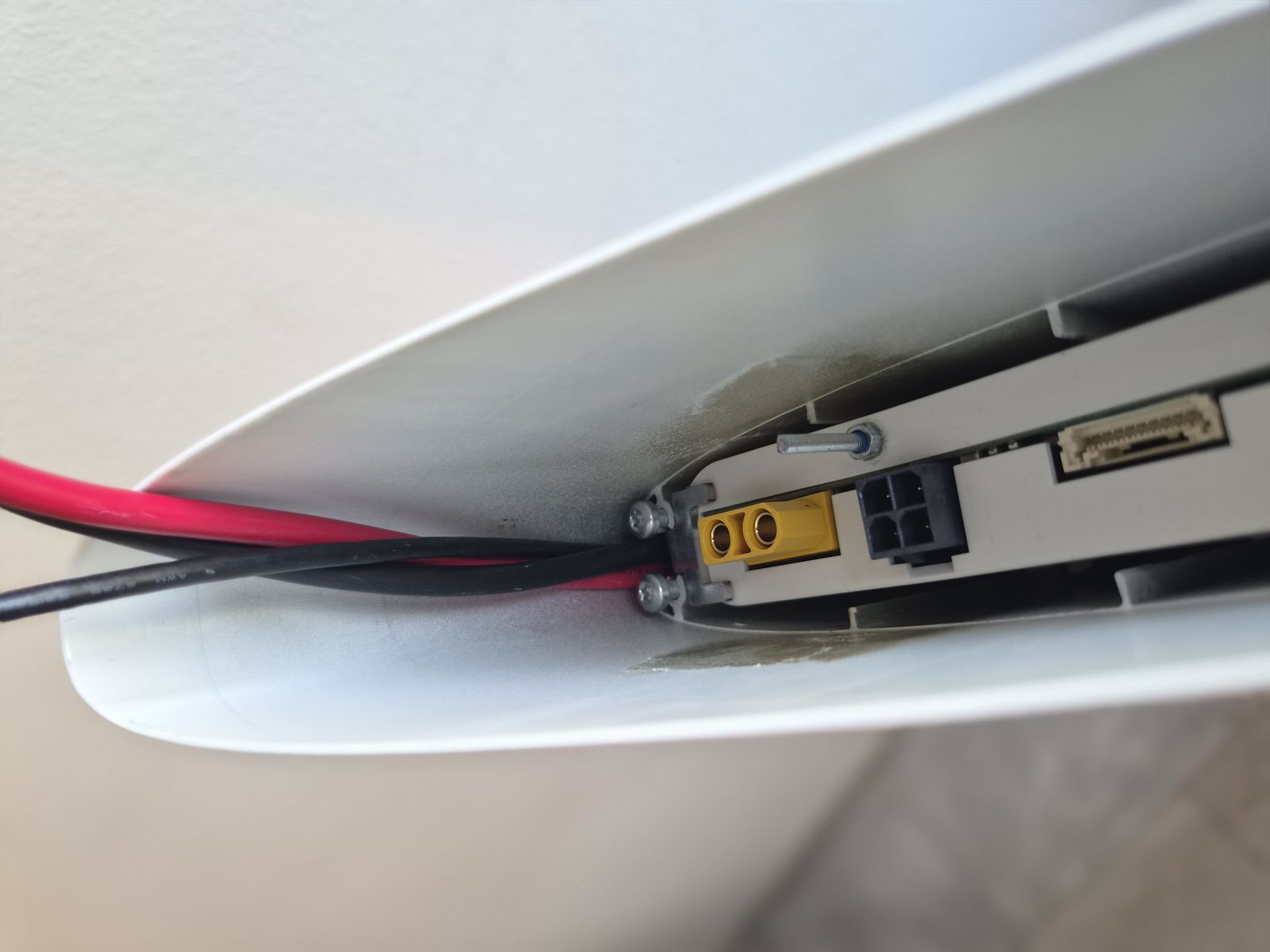
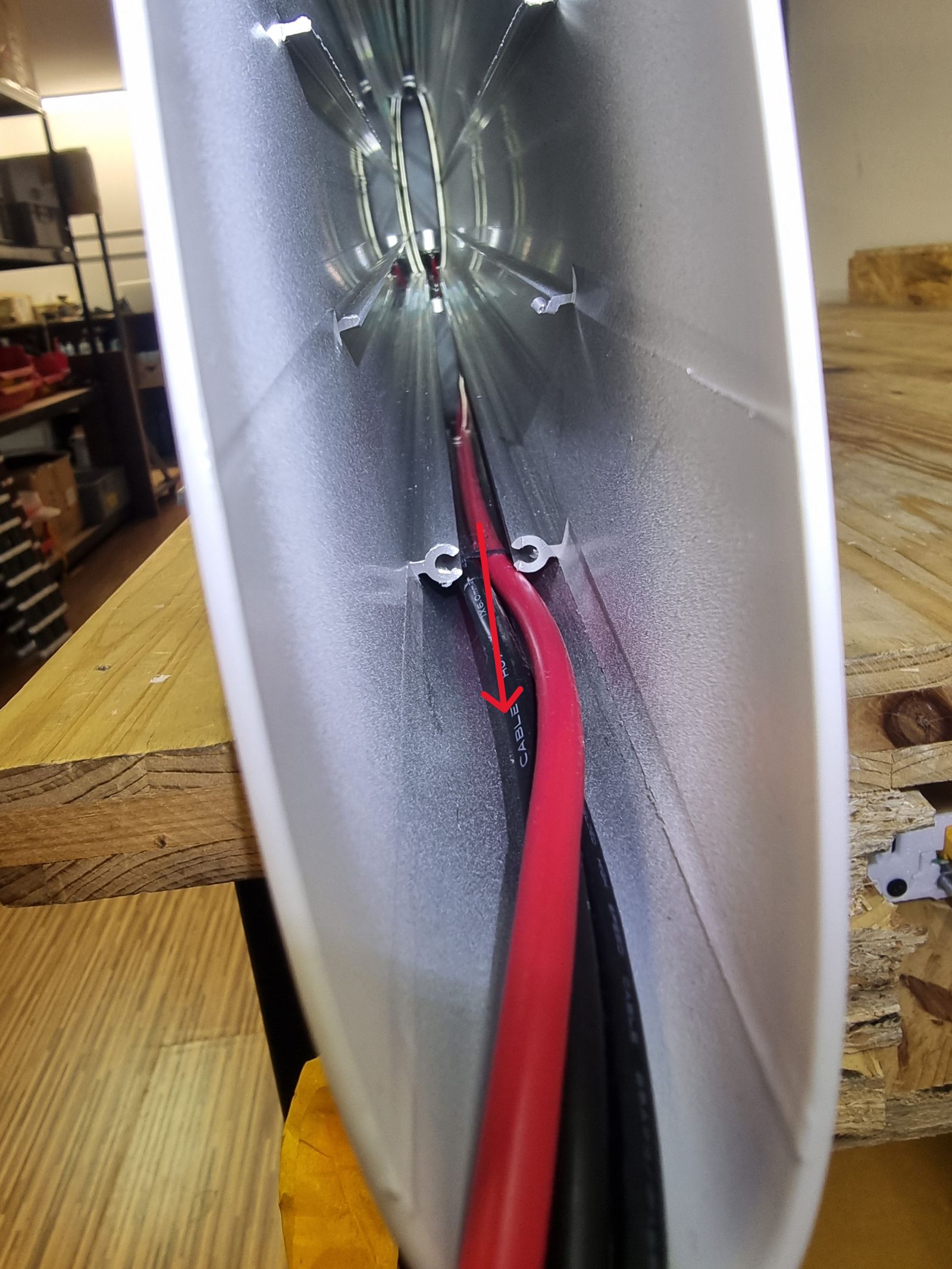
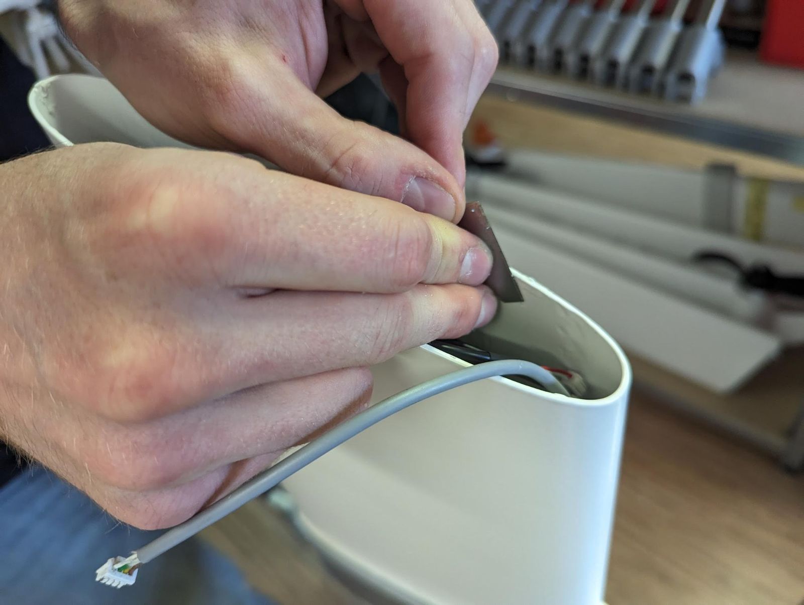
IB-DIS-013 DISASSEMBLY STEP 13 - Remove plastic cable duct and cables
Tools:
Removing parts:
Procedure:
Link to original
- Pull the plastic cable duct out of the housing channel.
- Remove the cables from the channel.
- If the cables cannot be removed, disconnect them from the motor controller first as described in RemigoOne Go&DE2 Drivetrain Service Manual.
IB-DIS-014 DISASSEMBLY STEP 14 - Clean silicone from motor housing
Tools:
Consumables:
Removing parts:
- No parts removed in this step.
Procedure:
- Remove the remaining silicone from the inside of the motor housing.
- Clean the sealing surface with isopropanol.
- Inspect the sealing surface for cuts, scratches or remaining silicone.
Link to originalCAUTION
The sealing surface must be clean and undamaged before assembly.
Check
IB-CHK-001 CHECK STEP 1 - Inspect removed interface and connectors
Tools:
- No tools required.
Procedure:
- Inspect the motor housing sealing surface for residual silicone, cuts, scratches or other damage. Re-clean if needed before reassembly.
- Inspect the interface connectors and signal/charge cables for corrosion, damage or bent pins.
- Inspect the Bungie cord used to secure the interface during silicone curing (see IB-ASM-009 ASSEMBLY STEP 9 - Attach first bungee cord point) and its mounting points for wear, cracking or damage.
CAUTION
🗑 Do not reuse the removed Interface assembly GO (120020002) / Interface assembly DE2 (120020003) (select the correct variant for the unit). Cutting the silicone seal during removal compromises its watertight seal — always install a new interface assembly.
Link to originalTODO
Add a dedicated photo showing the sealing surface and connectors being inspected, separate from the disassembly/reassembly action photos.
Define acceptance criteria for cable/connector wear (e.g. corrosion limits, pin damage tolerance, minimum bungee cord condition).IB-CHK-002 CHECK STEP 2 - Inspect battery pack and connectors
Tools:
- No tools required.
Procedure:
- Inspect the removed battery pack for swelling, deformation, corrosion or damaged cables.
- Inspect the motor cable connector and battery fixing plates for damage or corrosion.
- Inspect the housing channels the battery slides into for debris or damage.
CAUTION
🗑 Do not reuse a swollen, deformed or damaged Battery pack (706020002). See Safety instructions — “Handling a damaged or swollen battery” — for isolation, storage and disposal.
Link to originalTODO
Define the acceptance criteria for battery pack condition (e.g. voltage/capacity check, swelling tolerance) before deciding whether a removed battery can be reinstalled.
Interface and battery assembly
IB-ASM-001 ASSEMBLY STEP 1 - Route motor cables
Tools:
- No tools required.
Installing parts:
Procedure:
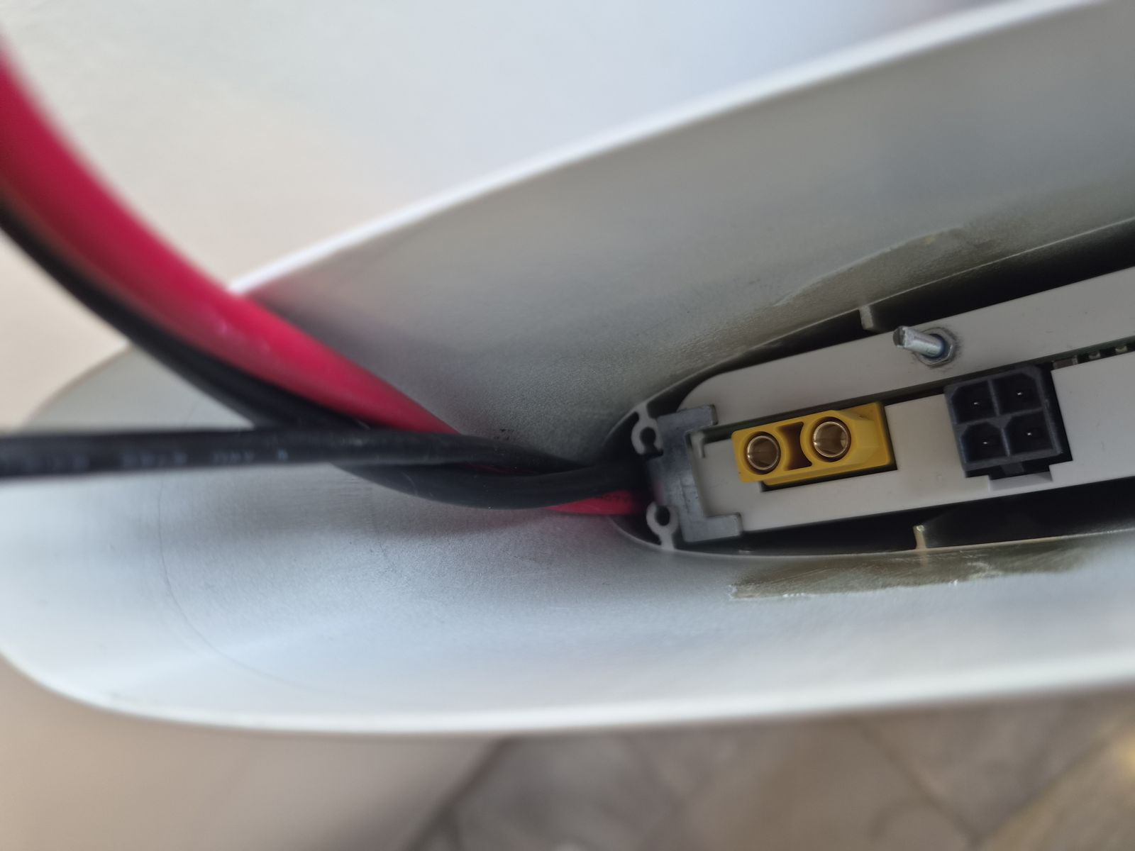
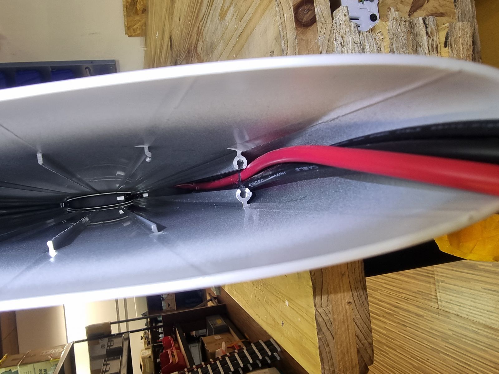
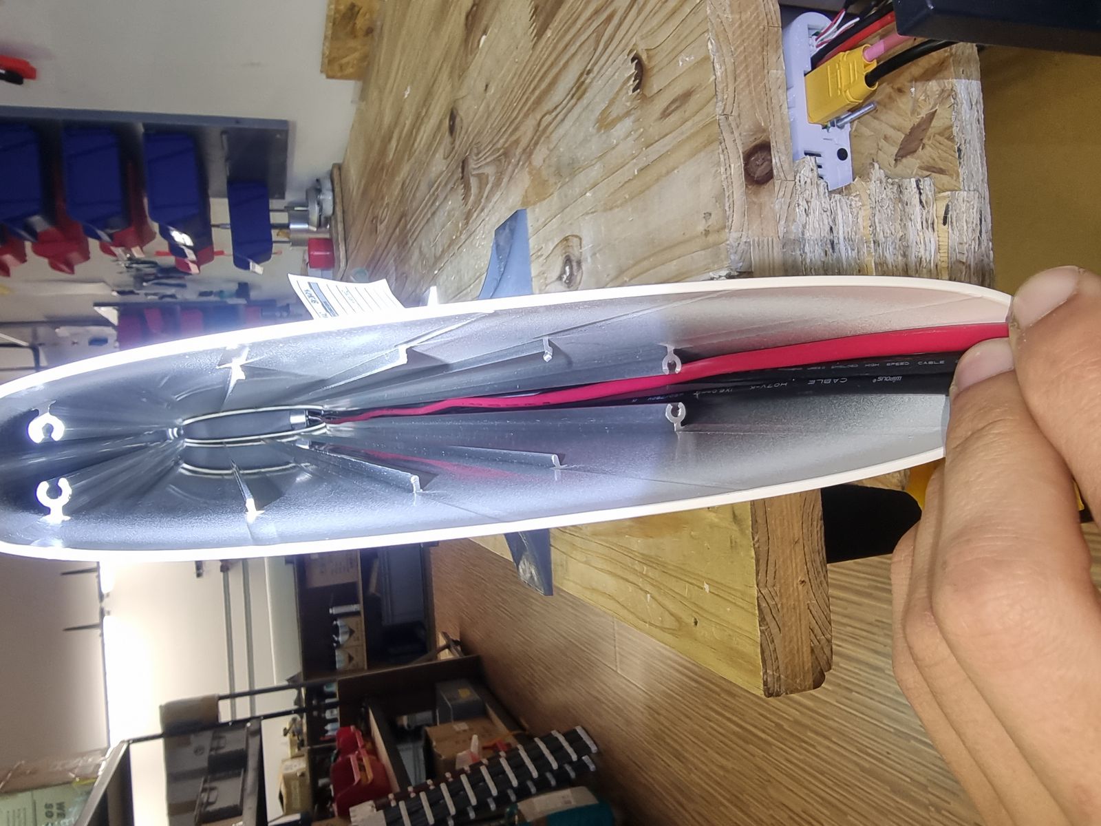
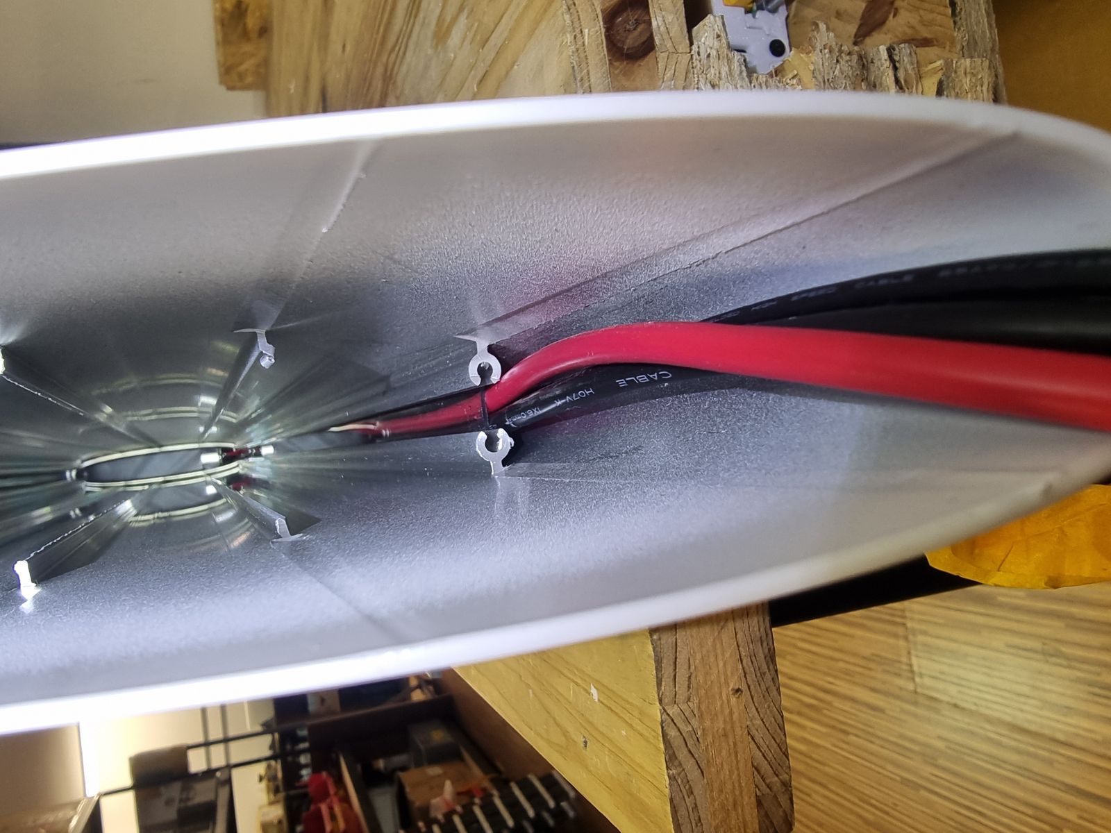
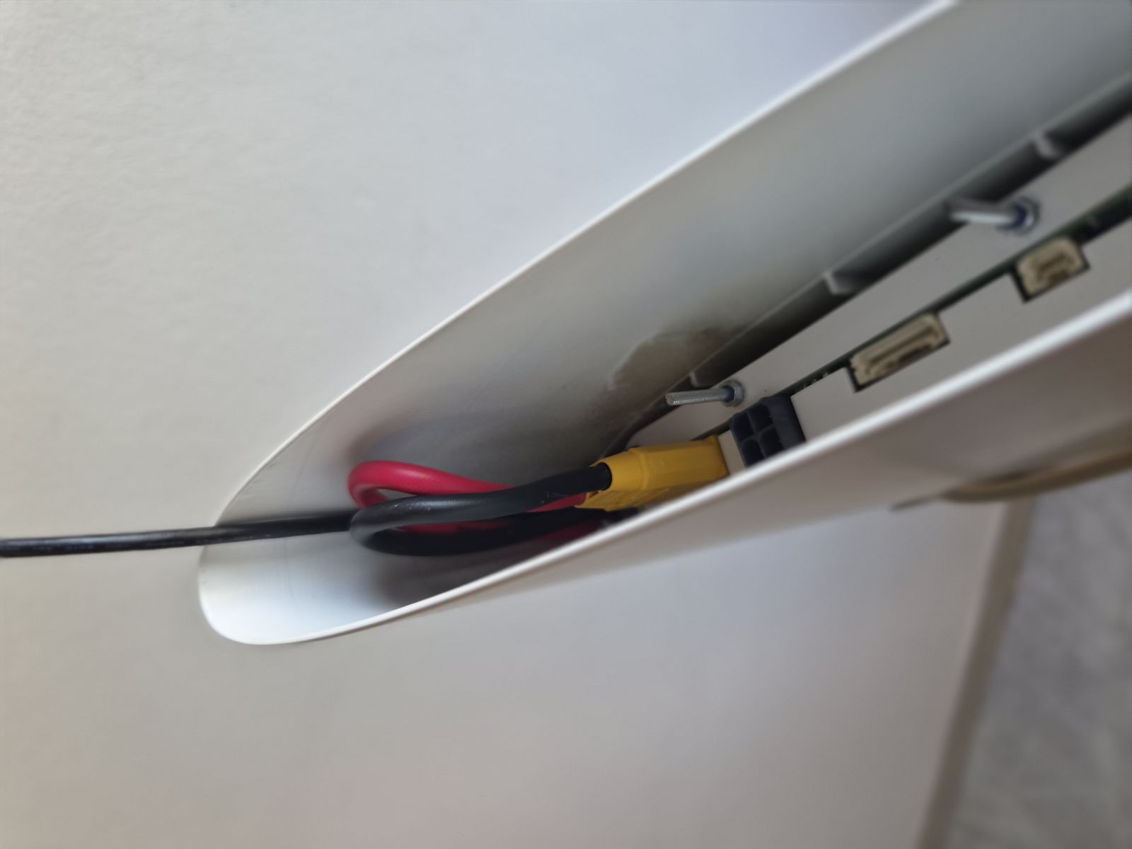
- Position the signal cable deepest in the channel.
- Place the power cables on top of the signal cable.
- Make sure the power cables run in a straight line.
Link to originalCAUTION
Incorrect cable routing can make battery installation difficult and can damage the cables.
IB-ASM-002 ASSEMBLY STEP 2 - Install plastic cable duct
Tools:
Installing parts:
Procedure:
Link to original
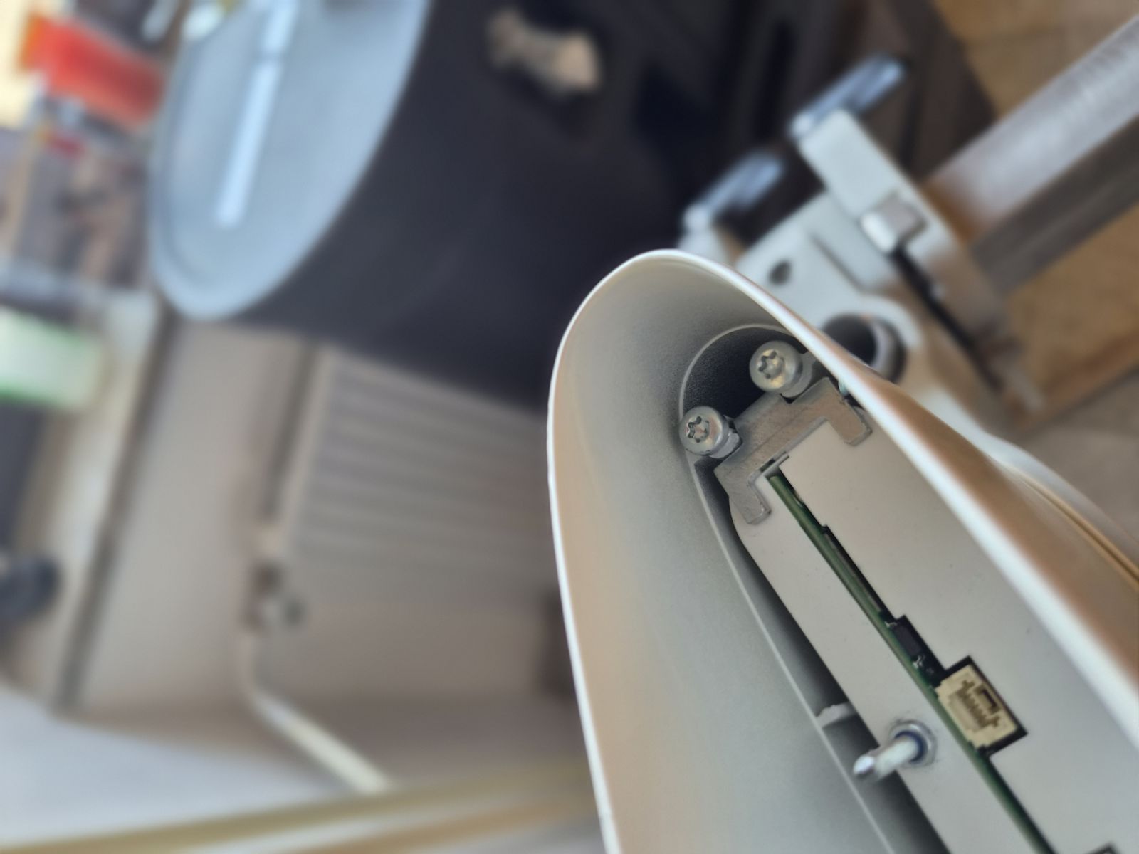
- Insert the plastic cable duct into the two aluminium channels.
- Use needle-nose pliers for easier insertion if required.
- Make sure the plastic cable duct is fully inserted as shown.
IB-ASM-003 ASSEMBLY STEP 3 - Insert battery pack
Tools:
Installing parts:
Procedure:
- Insert the battery pack into the housing using needle-nose pliers.
- Orient the battery terminal on the opposite side from the motor cables.
Link to originalCAUTION
Do not pinch or scrape the cables while inserting the battery. Make sure all cables are fully guided into their dedicated cable holders before sliding the battery in.
Check that the battery is correctly aligned with the housing channels. If it does not slide in easily, stop and re-check alignment rather than forcing it.IB-ASM-004 ASSEMBLY STEP 4 - Install cable protection plastic
Tools:
- No tools required.
Installing parts:
- Cable protection plastic
Procedure:
Link to original
- Slide the cable protection plastic over the installed plastic cable duct.
- Make sure it covers the cable duct in the battery insertion area.
IB-ASM-005 ASSEMBLY STEP 5 - Install battery fixing plates
Tools:
Installing parts:
Procedure:
Link to original
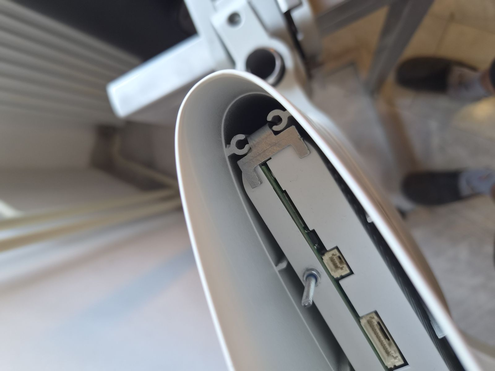
- Insert the battery fixing plate into the housing channels.
- Make sure the fixing plate is correctly seated.
- Repeat on the opposite side of the battery.
IB-ASM-006 ASSEMBLY STEP 6 - Tighten battery fixing screws
Tools:
Consumables:
- Permabond A126 (010010004) (only if a screw does not grip, see caution below)
Installing parts:
Procedure:
- Install the four M4x25 screws into the housing channels.
- Tighten the screws until the fixing plates compress the battery pack.
Link to originalCAUTION
Stop tightening when the fixing plates visibly compress the battery pack. Do not overtighten.
Work with the housing in a horizontal position. A dropped screw can fall into the battery or motor cavity and cause a short circuit.
If a screw does not grip because the housing thread is damaged, secure it with Permabond A126 (010010004) instead of continuing to force it.IB-ASM-007 ASSEMBLY STEP 7 - Connect motor cable to battery
Tools:
Installing parts:
- No parts installed in this step.
Procedure:
Link to original
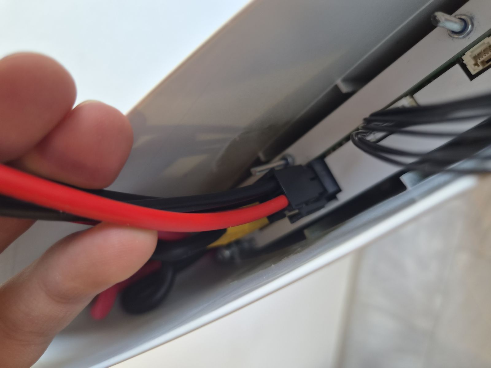
- Use needle-nose pliers to connect the motor cable to the battery connector.
- Tuck the power cables into the housing as shown.
- Make sure the cables are not under tension.
IB-ASM-008 ASSEMBLY STEP 8 - Connect interface cables
Tools:
Consumables:
Installing parts:
- Interface assembly GO (120020002) / Interface assembly DE2 (120020003) (select the correct variant for the unit)
Procedure:
- Plug in the signal cable connectors. The connectors are keyed and cannot be mismatched.
- Plug in the charge connector.
- Ensure all connector lock tabs are fully engaged.
- Apply a small amount of silicone to the back of the signal connectors.
Link to originalCAUTION
Do not apply silicone to connector contact surfaces.
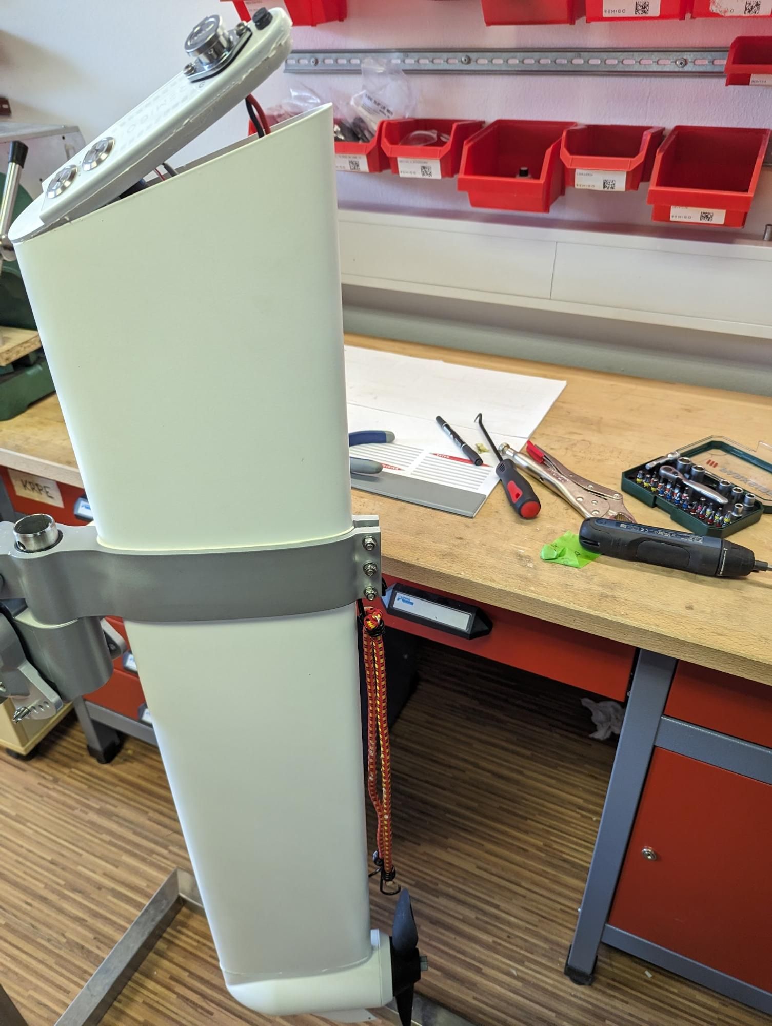
IB-ASM-009 ASSEMBLY STEP 9 - Attach first bungee cord point
Tools:
Installing parts:
- No parts installed in this step.
Procedure:
Link to original
- Attach one side of the bungee cord to the tiller bolts.
- Keep the bungee cord ready for holding the interface after silicone application.
IB-ASM-010 ASSEMBLY STEP 10 - Clean sealing surfaces
Tools:
- No tools required.
Consumables:
Procedure:
- Clean the sealing surface of the interface with isopropanol.
- Clean the sealing surface of the motor housing with isopropanol.
- Make sure both surfaces are dry before applying silicone.
Link to originalCAUTION
Silicone must be applied only to clean and dry sealing surfaces.
IB-ASM-011 ASSEMBLY STEP 11 - Apply silicone to interface
Tools:
Consumables:
Procedure:
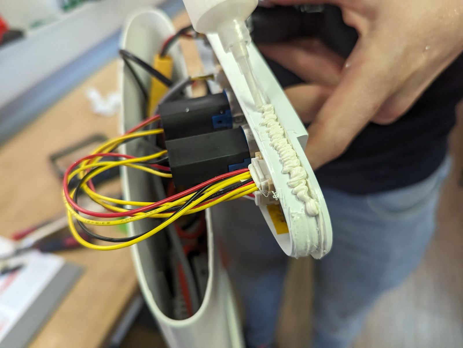
- Apply a continuous bead of silicone to the interface sealing surface.
- Make sure the silicone is applied around the full sealing perimeter.
- Avoid gaps in the silicone bead.
Link to originalCAUTION
Missing silicone on the sealing perimeter can cause leakage.
IB-ASM-012 ASSEMBLY STEP 12 - Spread silicone on sealing surface
Tools:
- No tools required.
Consumables:
- Rubber gloves
Procedure:
Link to original
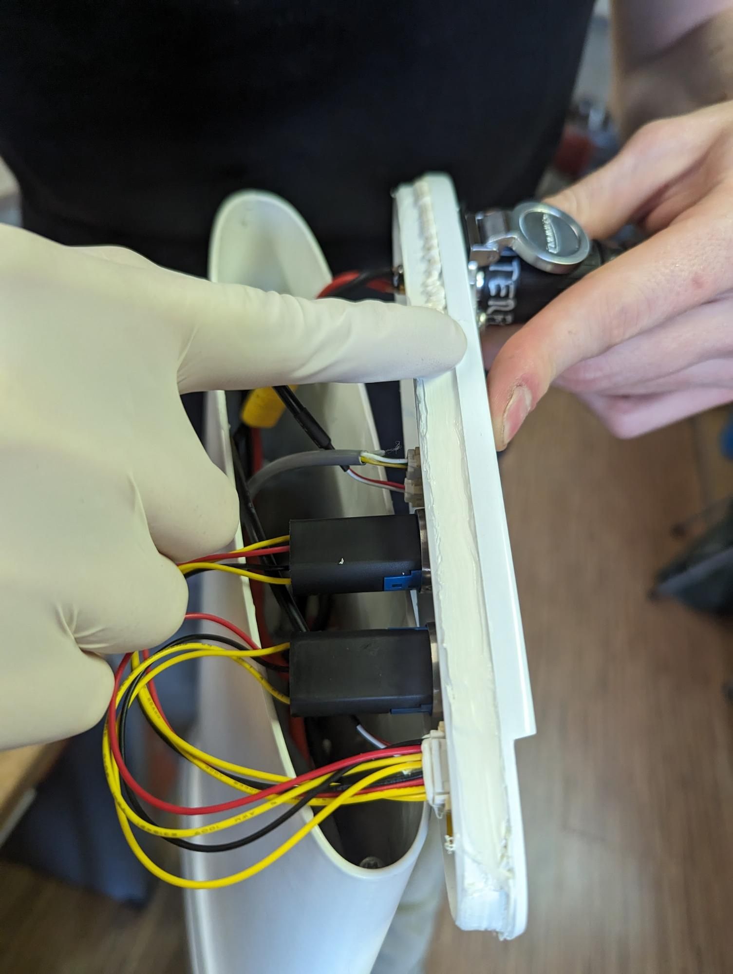
- Put on rubber gloves.
- Spread the applied silicone evenly around the mating surface with a gloved finger.
- Keep the silicone layer continuous around the full perimeter.
IB-ASM-013 ASSEMBLY STEP 13 - Install interface
Tools:
- No tools required.
Installing parts:
- Interface assembly GO (120020002) / Interface assembly DE2 (120020003) (select the correct variant for the unit)
Procedure:
- Position the interface on the motor housing.
- Press the interface down firmly.
- Hold the interface in position until it is secured with the bungee cords.
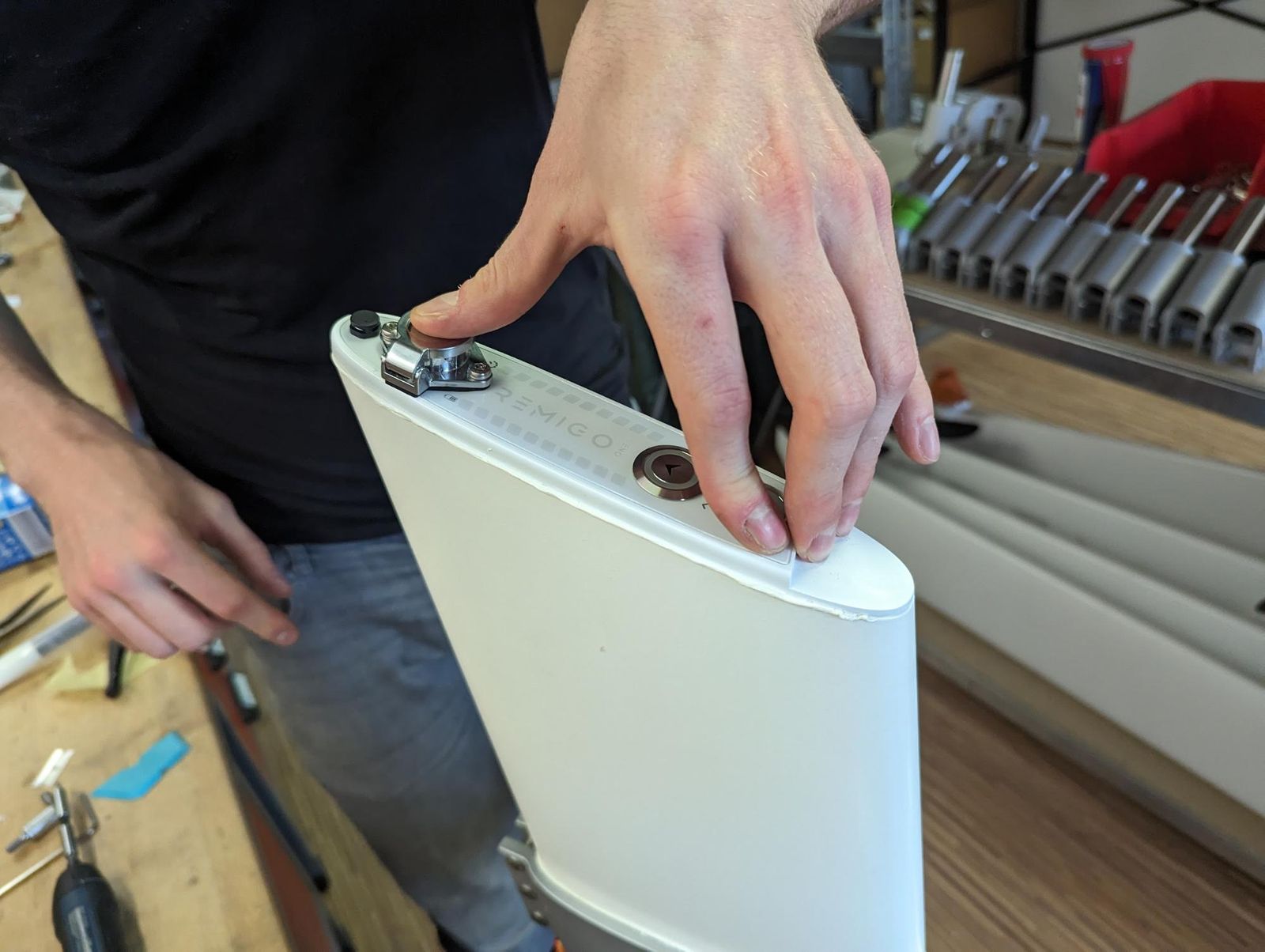
- Check that a small amount of silicone squeezes out around the edge.
Link to originalCAUTION
If no silicone squeezes out, remove the interface, clean the sealing surfaces and repeat the sealing procedure from assembly step 10.
IB-ASM-014 ASSEMBLY STEP 14 - Remove excess silicone
Tools:
Procedure:
Link to original
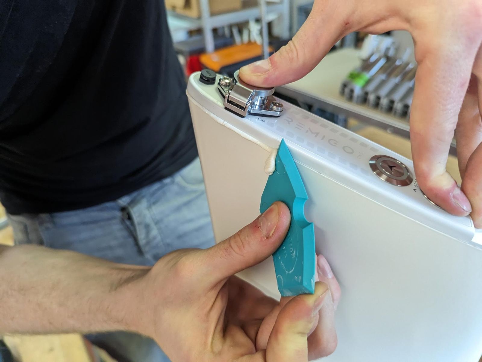
- Scrape away excess silicone with the silicone squeegee.
- Do not disturb the interface position while removing excess silicone.
IB-ASM-015 ASSEMBLY STEP 15 - Secure interface with bungee cords
Tools:
Procedure:
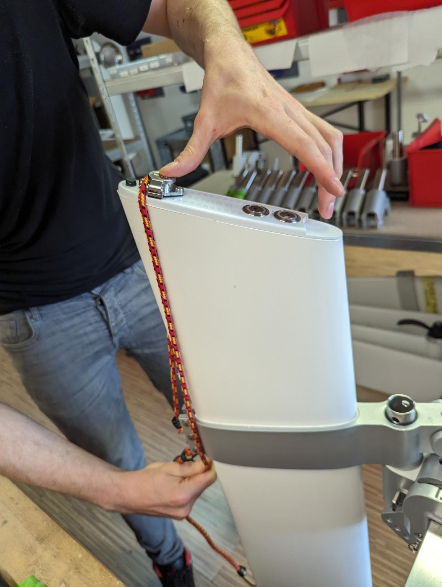
- Attach the bungee cords over the interface.
- Apply as much tension as possible without shifting the interface.
- Route the first bungee cord between the charging socket and screw.
- Route the second bungee cord over the kill switch surface.
Link to originalCAUTION
Make sure the bungee cords hold the interface evenly against the housing during curing.
IB-ASM-016 ASSEMBLY STEP 16 - Check bungee cord position
Tools:
- No tools required.
Procedure:
Link to original
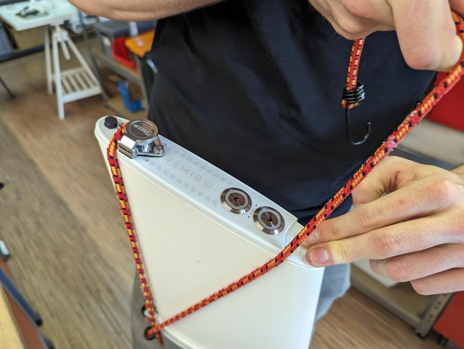
- Check that the first bungee cord is routed between the charging socket and screw.
- Check that the second bungee cord is routed over the kill switch surface.
- Verify that the interface is still fully seated.
IB-ASM-017 ASSEMBLY STEP 17 - Final silicone cleanup and curing
Tools:
Consumables:
- Paper towel
- Mild window cleaner
Procedure:
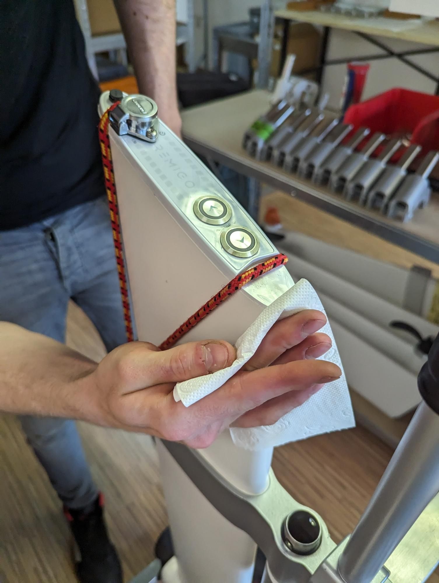
- Wipe away any remaining silicone from the outboard.
- Take extra care in the areas directly below the bungee cords.
- Leave the assembly to cure for at least 48 h at room temperature.
- After curing, scrape away any remaining silicone.
- Clean the interface with a cloth and mild window cleaner for the final finish.
Link to originalCAUTION
Do not remove the bungee cords or move the interface before the silicone has cured.
Color key
Blue = Disassembly · Red = Check · Green = Reassembly